杨雪梅,张 瑞*,石 金,吴 琼,杜伟豪,王志斌,李孟委
(1. 中北大学 山西省光电信息与仪器工程技术研究中心,山西 太原 030051;
2. 中北大学 前沿交叉科学研究院,山西 太原 030051;
3. 中北大学 南通智能光机电研究院,江苏 南通 710065)
The detection of the parameters of incoming laser is associated with an important and constantly expanding group of security,military,aircraft,and satellite safety systems[1]. Over the last century,the development of laser detection technology has become one of the most debated issues surrounding the protection of strategic centers against various laser sources,such as continuous-wave lasers and pulsed lasers[2]. Therefore,a laser detection system has been designed to identify a threat,collect information accurately,and issue warnings promptly. Furthermore,this system can combine excellent electronic devices with advanced optical technologies[2]. Recently proposed laser detection systems can be classified into three categories:coherent recognition,scatter recognition,and spectrum recognition[3-5]. Spectrum recognition can also be categorized depending on the involvement of imaging. Primarily,the imaging laser detection system consists of a wide-angle fisheye lens and a charge-coupled device(CCD) photodetector[6-7].The most significant advantage of this method is that full air space can be monitored with high orientation accuracy,but without scanning[8]. However,this detection system cannot identify the laser wavelength,which is detrimental to determining the type of a laser threat[8].
Another methodology involves the application of quadrant photodetectors or discrete point detectors located within a selected geometry[9].For sensors of this type,the ratios of received powers(and related photocurrents)accommodate the evaluation of the incoming radiation for its angle[9]. However,in most circumstances,such solutions suffer from a limited field of view,low angular resolution,susceptibility to the background,and heavy reliance on beam irradiance distribution[10]. Furthermore, despite being perfectly Gaussian in the early stages,a laser beam is affected by refractive index spatial inhomogeneities(turbulence)after travelling hundreds of meters in the atmosphere. This phenomenon can distort the wave front and lead to irradiance inhomogeneities[10].
Recently,a novel method was proposed to recognize the incident angle and laser wavelength in a large field of view(FOV)[10]. In this system,a large field-of-view lens is combined with a sinusoidal amplitude grating[11]. First,the system"s directional resolution is determined by the angular accuracy of the hardware characteristics exhibited by imaging devices,such as the FOV of the lens and the resolution of imaging[12]. Subsequently,a lens is designed to cover this wavelength range,which is significant for improving the capability of the imaging laser detection system[12]. The objective of this article is to provide a lens and grating for an imaging laser detection system[13]that can supposedly detect rays in both the visible and NIR spectra(wavelength of laser threats)[14]. The inverse-telephoto objective lens was applied as a first-order design to reduce the angle of the incident ray[14]. Finally,the results of the proposed structure were examined using ZEMAX optical design software[15]. Based on the free mirror proposed in the Netherlands last year,the laser-warning system has a detection accuracy of more than 1°,which falls far short of the laser detection requirement[15]. Here,a large field-of-view lens and wide-spectrum grating were taken as the primary originals to achieve high-precision two-dimensional laser warnings.
The laser-warning system adopted a modular structure,as shown in Figure 1. Therefore,it is advantageous for comprehensively detecting the incoming laser owing to its wavelength,azimuth,pitch angle,and pulse width. Figure 2 shows the optical path diagram of the detection of the incoming laser based on broadband grating. The system consists mainly of broadband black-white grating,a lens,a multi-narrowband filter,and a visible and near-infrared area array detector (CCD),which is placed on the focal plane of the lens.This diagram shows that the CCD imager records the spots once the lens detects the laser beam.Subsequently,the direction and wavelength of the incoming laser beam can be determined using the coordinates of the imaged spots through an image processing circuit system.

Fig.1 Overall system module diagram
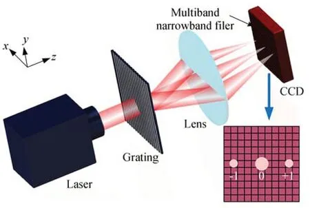
Fig.2 Light-path map of incident laser detection
A black-white grating diffracts the incoming ray while the lens is imaged on the area array detector. Figure 3(a)shows the projection of the incoming laser beam along thexz-plane,which is used to measure the azimuth angleα. The projection in theyz-plane is used to measure the pitch angleγ,as shown in Figure 3(b).
After entering the optical system,the incoming beam is diffracted by a broadband black-white grating before passing through a broadband,large field of view,achromatic lens to converge the diffracted beam on the CCD at the focal plane and image,thus forming a light spot. As shown in Figure 3(a),the position of the 0 diffraction order spectrum is denoted byx0,that of the 1 diffraction order spectrum is indicated byx+,that of the-1 diffraction order spectrum is indicated byx-,the 0 diffraction order angle is represented byα,and the 1 and-1 diffraction order angles are expressed as β+and β-,respectively,which can be obtained using Equation(1).

Fig.3 Schematic of two-dimensional angle measurement based on wide spectrum grating diffraction
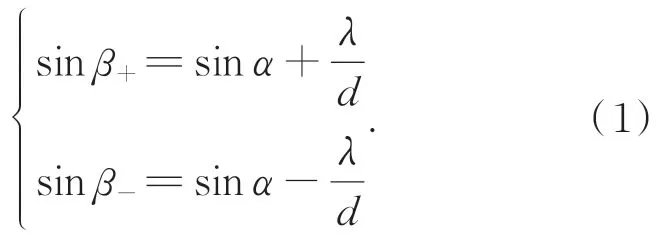
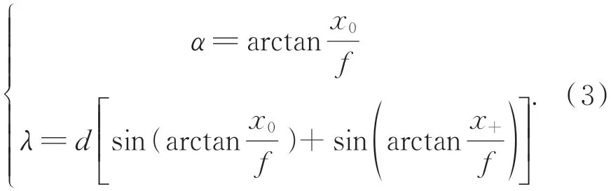
The CCD was placed at the focal plane of the lens,and the spot information,as imaged on the CCD,was processed. Thus,the positions ofx0,x+,andx-can be obtained as follows:

Considering Equations(1)and(2):
The angle of interest,γ,(Figure 2(b))can be inferred using the same principle:
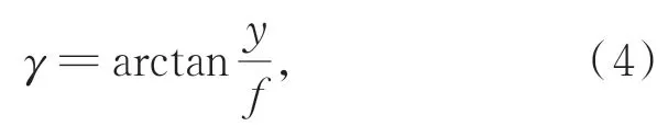
wheredrepresents the grating period,andfrefers to the focal length of the lens.
3.1 Optical lens design
The laser-warning system studied here can measure the beam for its wavelength,azimuth angle(α),and pitch angle(γ). It can detect wavelengths of up to 0.5-1.7 μm,and the laser center wavelength detection accuracy is better than 8 nm. Meanwhile,the azimuth can attain 95° ,whereas the pitch angle can attain 72°. Ultimately,the angular error is greater than 0.7°. The CCD chosen for this study was supplied by the Shanxi Guohui Optoelectronics Technology Co.,Ltd. Figure 4 shows some indices of the CCD that can detect the spectrum from visible to NIR wavelengths. This is effective for broadening the detection range.
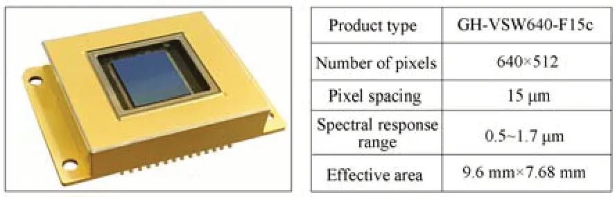
Fig.4 Visible-NIR broadband detector index parameters
After the laser beam enters the general optical imaging system,a phase difference arises owing to the variation in lens thickness,thus achieving the focusing and imaging function of the lens.Moreover,there are certain requirements regarding the shape and thickness of the lens to improve its functioning. This study aimed to simultaneously detect laser beams with a broadband and a large field of view. In general,it is difficult to achieve this without an effective solution. Thus,a negative meniscus lens is required to reduce the maximum laser-beam angle and steer the beam away from the entire hemisphere to the end of the lens.
Furthermore, multiple negative elements were used in the front group of the lenses to further reduce the angle of the laser beam. Therefore,a broadband and wide-field achromatic lens was designed. The ZEMAX optical automatic design software was applied according to the required parameters of the first-order model,and the merit function was used to perform the primary optimization. Thus,a high-resolution lens produces excellent performance in the context of visible and infrared spectra. Figure 5 illustrates the optical layout of the designed lens,which has a diagonal field of view of up to 150°. By contrast,Figure 6 shows the corresponding diffused spots of laser beams with different wavelengths and directions.

Fig.5 Optical layout of designed lens
Table 1 shows the size of the diffused spots corresponding to different spectra. The size of the full-spectrum spot is smaller than 30 μm,and the spot radius meeting our requirements is smaller than the size of the two pixels of the detector. The root mean square(RMS)is a requisite parameter to evaluate an optical system"s performance. According to this diagram,the maximum RMS is 10.1 μm,which means that the system can achieve the resolution required to provide highquality images in the visible and near-infrared wavelengths range.
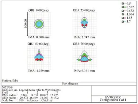
Fig.6 Spot diagram

Tab.1 Size of diffuse spots in different spectra
Modulation transfer function(MTF),one of the most comprehensive standards for evaluating lens quality,illustrates the modulation of an optical system from an object to an image as a function of spatial frequency,ranging between 0 and 1.Specific spatial frequency and aperture parameters were set to obtain the MTF images. The spatial frequency was set to 30 pairs/mm. The MTF curves are shown in Figure 7. The closer the MTF value is to 1,the better the lens performance. Figure 7 shows the MTF characteristics of the lens for visible and infrared wavelengths. It can be observed from this figure that the MTF value of the lens invariably exceeded 0.4,indicating that the overall characteristics of the lens were satisfactory. A broadband,large field of view,achromatic lens was constructed based on this design,as shown in Figure 8. The lens has an aperture of 2.0 and a pupil diameter of 36 mm.
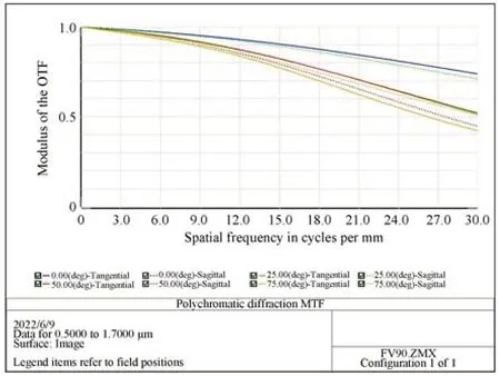
Fig.7 MTF curve

Fig.8 Image of achromatic lens with broadband and large field of view
3.2 Broadband black-white grating design
In line with these requirements,a broadband black-white grating of 32 mm × 32 mm and grating period of 2.5 μm was designed. The duty cycle of the designed grating is 0.6. A schematic of the grating structure is presented in Figure 9.Compared with the traditional sinusoidal amplitude grating,this black-white grating has easy processing.

Fig.9 (a)Structure diagram of broadband black-white grating and physical diagram,(b)Actual broadband black-white grating apparatus.
The method discussed was implemented in the simulation. A multi-narrowband filter was used to filter out the interference of background light,and the filter was replaced according to the detection requirements. Without background-light interference,it is possible to add filters. Figure 10 shows the transmittance curve of the filter used in the experiment. MATLAB software was used to simulate the intensity of the laser beam at different wavelengths and incident angles. In the visible and infrared spectra,the laser beam wavelength was set to 532,632,1 064,and 1 550 nm for simulation. The simulation results obtained when the incident angle was 0° are shown in Figure 11. For the field of view of 95°,both the 0 1 and-1 diffraction order spots could be detected when the laser was incident at the maximum wavelength.The simulation results obtained for the incident angle of 48° are shown in Figure 12;
a minimum of two spots are observed on the detector when the maximum wavelength of the laser is incident. According to the simulation diagram,the normalized intensity of ±1 diffraction order spots is in 50%excess,while the diffracted 0 order and ±1 order light intensities starkly differ. Consequently,the 0 and ±1 order spots can be effectively distinguished when the laser diffraction spot is imaged on the CCD. After processing the electrical signal on the CCD using a high-speed signal-processing circuit,information,such as the wavelength and direction,of the incident laser beam can be obtained.
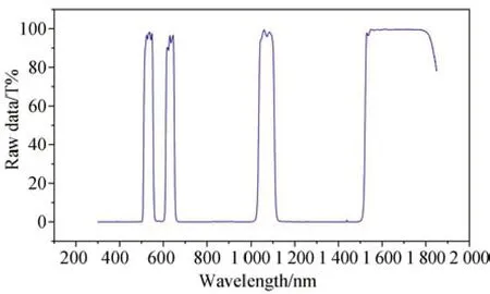
Fig.10 Transmittance curve of multi-narrowband filter used in laser-warning system
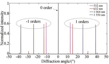
Fig.11 Normalized intensity of 0 and ±1 diffraction order spots with laser incident angle of 0°
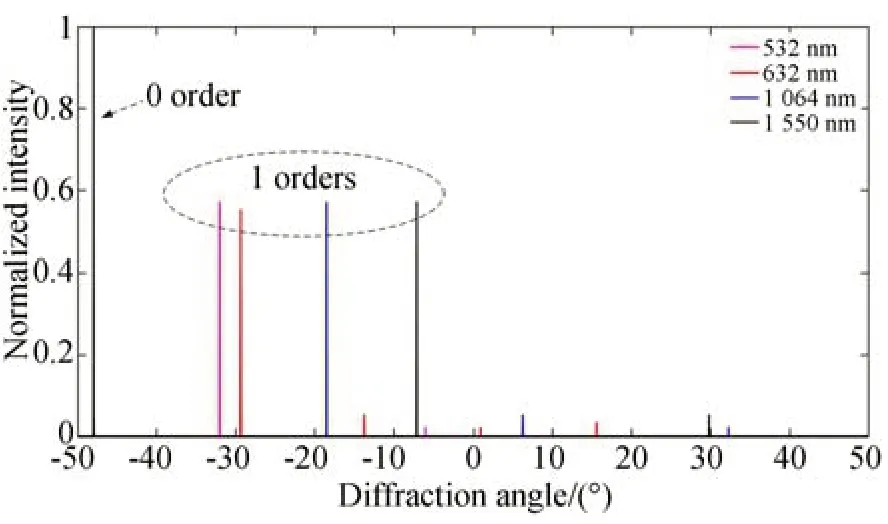
Fig.12 Normalized intensity of 0 and 1 diffraction order spots with laser incident angle of 48°
The broadband black-white grating period used here was 2.5 μm. The size of the CCD is 9.6 mm × 7.68 mm,the number of pixels is 640× 512,and the area of each pixel is 15 μm × 15 μm. The results are shown in Figures 13 and 14.The theoretical wavelength resolution of the incident laser beam is lower than 8 nm,while the angle resolution can attain 0.18°. In addition,this design can detect an azimuth of up to 95° and a pitch angle of up to 72° for an incident laser beam.However,given the experimental environment and algorithm errors,the angle error could still be maintained at a level higher than 0.7°.
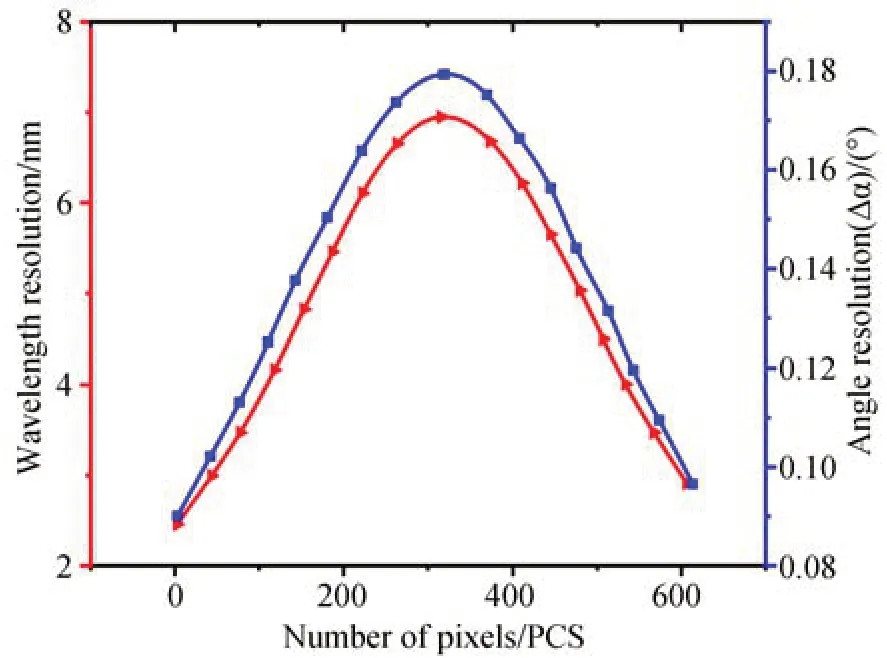
Fig.13 Wavelength and angle resolutions

Fig.14 Detectable azimuth and pitch angle range
Multiple ultra-narrowband filters were used to filter the light source into monochromatic light for the simplicity of the experiment. The beam wavelengths were set to 532,1 064,and 1 550 nm. The experimental equipment and results are shown in Figure 15. As shown in Figure 15(b),15(c),and 15(d),a comparison was performed for the spot positions after beam diffraction with different wavelengths at the same incident angle.Figure 15(d)and 15(d)present a comparison of the spot positions after beam diffraction for the same laser wavelength but different incident angles. Regardless,the detector can detect the zero and one-diffraction order spots of the incident beam. Finally,after beam diffraction,the spot position information was processed by the DSP algorithm and high-speed signal processing circuit to obtain the angle,wavelength,and other details of the incident laser beam. A portion of the experimental data is presented in Table 2. The detection errors of the angle and wavelength can be expressed as follows:

whereαandγdenote the azimuth and pitch angles of the turntable,respectively,andα" andγ" represent the measured actual azimuth and pitch angles,respectively. In addition,Δαand Δγrepresent the azimuth and pitch angle errors,respectively.λrepresents the central wavelength of the laser,λ" represents the measured wavelength,and Δλrepresents the central laser wavelength error.It can be concluded from Table 2 that the maximum angular error is 0.6° and the maximum central laser wavelength error is 7 nm. We can draw the following important conclusions from these values:the optical angle error is better than 0.7°.Simultaneously,the laser center-wavelength detection accuracy was better than 8 nm. Thus,high-precision laser warnings can be obtained.

Fig.15 Experimental setup and spots information acquisition map

Tab.2 Part of the experimental data
Here,we designed an optical system with a broadband,large field of view,achromatic optical lens and broadband black and white grating to achieve high-precision detection of the two-dimensional angle of the incoming laser. According to the simulation and experimental results,the maximum measuring azimuth of the system could attain 95°,and the pitch angle could attain 72°. In addition,the detectable spectral range was expanded to 0.5-1.7 μ m. Compared with the existing laser-warning system,this design achieved a large field of view,broadband,and high-precision detection simultaneously. The error angle was better than 0.7°,and the central laser wavelength detection accuracy was better than 8 nm. These effectively improved the reliability of laser warnings. In the future,the lens and grating designs will be optimized to further expand the detection field of view and improve detection accuracy.
猜你喜欢 南通太原研究院 北京食品科学研究院肉类研究(2022年5期)2022-06-16《太原理工大学学报》第七届编委会太原理工大学学报(2022年1期)2022-01-29乡村振兴“太原模式”亮起来今日农业(2021年16期)2021-11-26太原清廉地图支部建设(2021年18期)2021-08-20陕西省红色文化教育研究院当代陕西(2021年13期)2021-08-06不是我!是他捣乱!动漫界·幼教365(中班)(2021年1期)2021-04-06南通籍华裔科学家高峰华人时刊(2021年21期)2021-03-09蓝印花布:南通独具特色的非遗传承华人时刊(2021年19期)2021-03-08非遗南通华人时刊(2020年19期)2021-01-14百企结对 携手并进:南通展现时代担当 致力推动跨江融合华人时刊(2020年19期)2021-01-14